All projects

Independent Project · Controls and Robotics

Self-Balancing Robot

Designed and built robot that used closed-loop feedback to detect changes in attitude and command its motors to remain upright.

  • Feedback Control
  • CAD
  • Embedded Systems
  • Hardware Testing
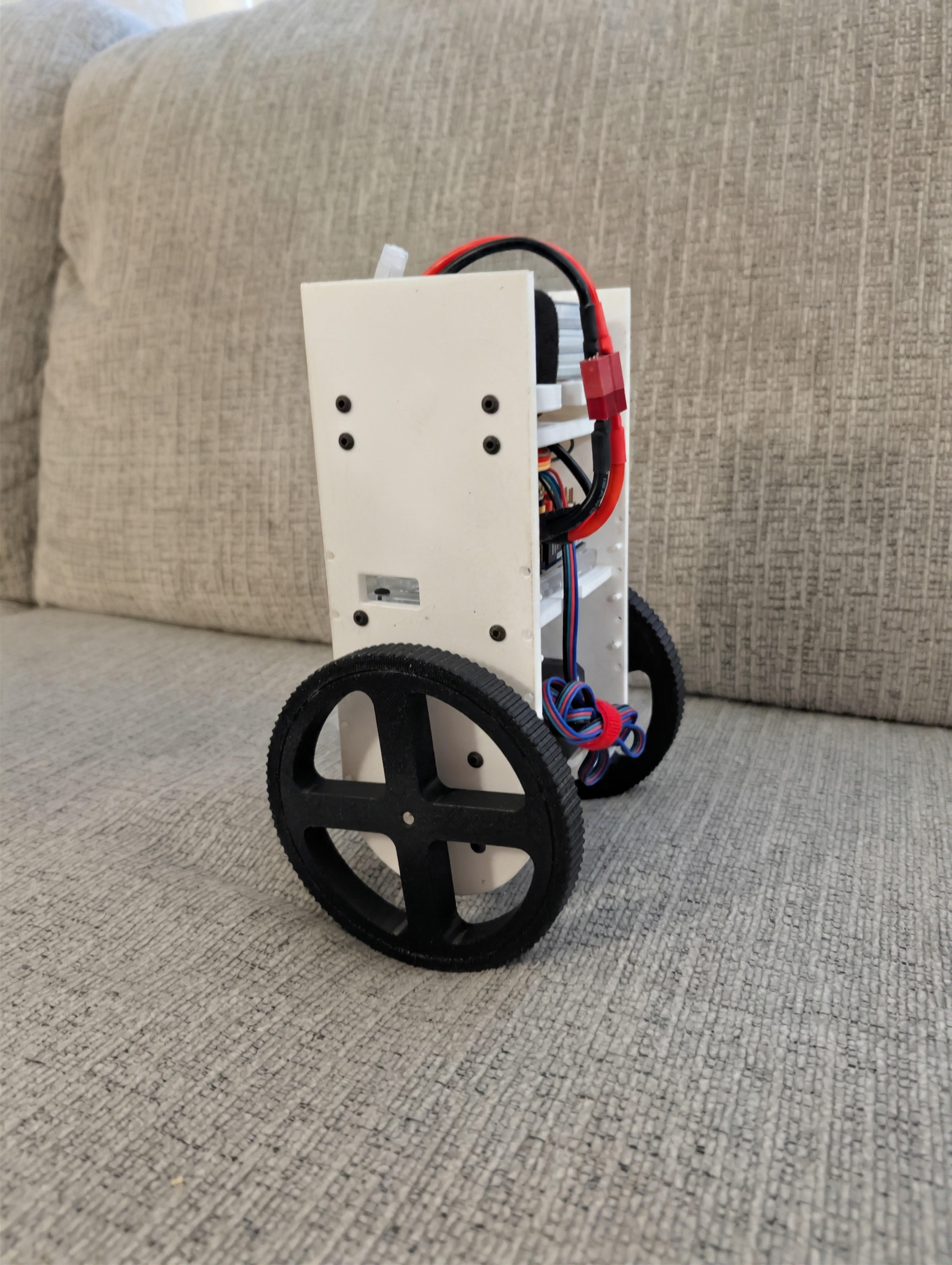
Self-balancing robot maintaining an upright position
The completed robot maintaining an upright position.
Independent Project development
Closed-loop Feedback control
CAD → Hardware Full build cycle
Self-balancing Final result

Project overview

Designing a complete balancing system

This project combined mechanical design, electronics, sensing, motor actuation, and feedback control in a compact robotic platform.

The robot continuously measured its attitude, calculated its deviation from the upright position, and commanded its motors to correct the motion before it fell.

My role

Independent development

I was responsible for the full development process, including CAD, component layout, mechanical assembly, wiring, control logic, software implementation, testing, and controller tuning.

Building the project independently required each mechanical, electrical, and software decision to work within the same physical system.
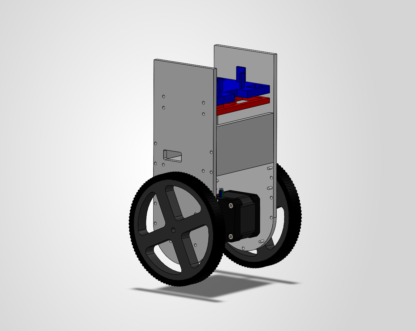
CAD model of the self-balancing robot
CAD design used to package the mechanical and electrical systems.

System design

How the robot balanced

Mechanical structure

The frame supported the electronics and positioned the mass, wheels, and motors around the balancing axis.

Attitude sensing

An onboard IMU measured the robot’s orientation and angular motion relative to its upright position.

Embedded control

The controller compared the measured attitude with the desired upright state and calculated a corrective command.

Motor actuation

The motors moved the wheelbase beneath the robot’s center of mass to oppose the direction of the fall.

Technical highlights

Feedback Control and Stability

Attitude feedback

Measuring the direction of the fall

0° Desired upright reference

The upright position was inherently unstable. Small attitude errors had to be detected quickly so the controller could respond before the robot moved beyond its recoverable range. PID control was utilized to correct the errors.

Motor control

Turning attitude error into motion

Feedback Sensor-to-motor control loop

When the robot leaned, the motors accelerated in the direction of the fall. This moved the wheelbase back underneath the center of mass and generated the corrective response needed to remain upright.

Controller gains were adjusted through repeated testing to balance response speed, stability, and motor behavior.

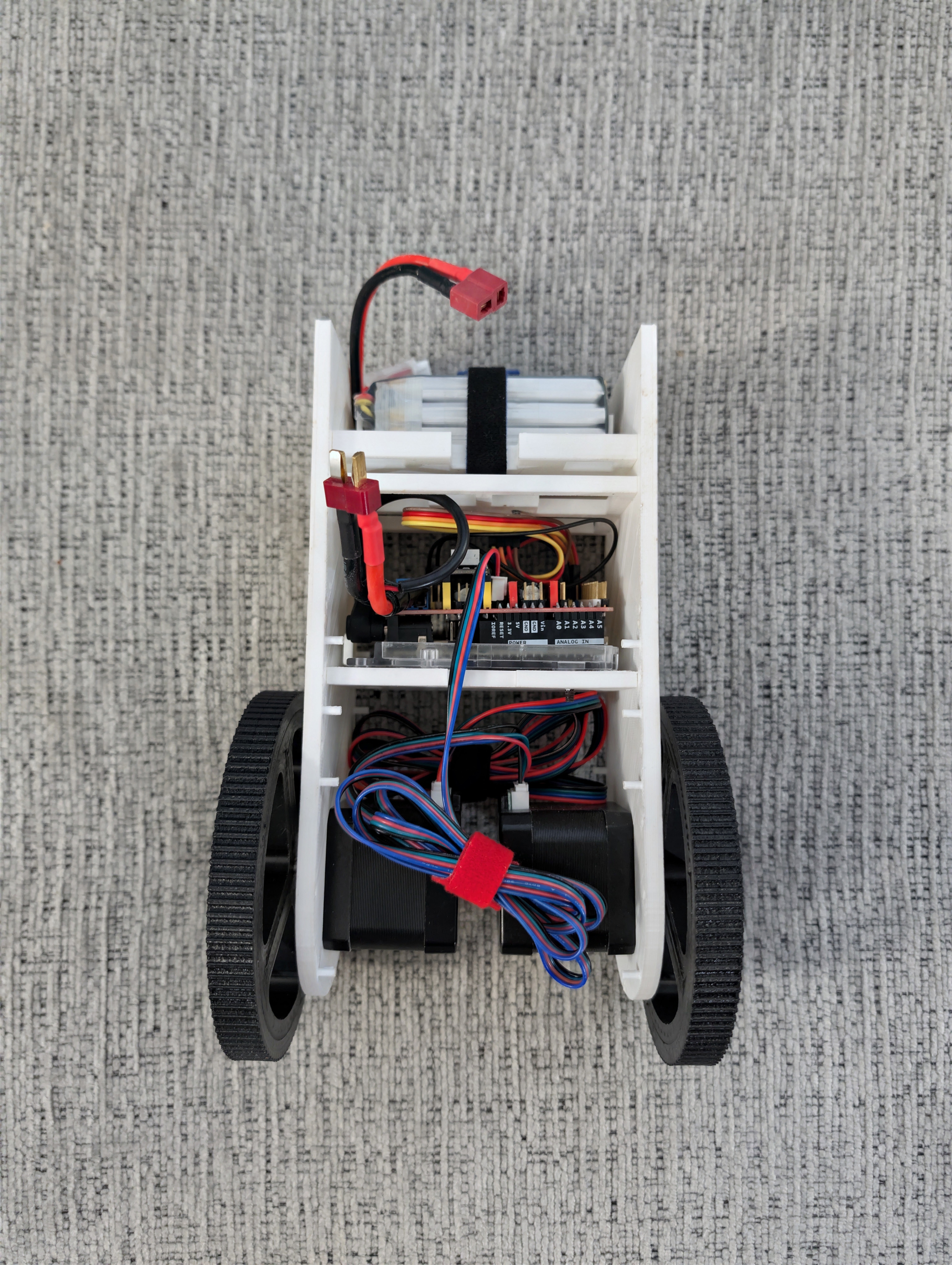
Self-balancing robot laid down with its internal components visible
Internal mechanical, electrical, and control components.

Testing and integration

Developing the complete robot

CAD and packaging

Planned the component layout and verified that the hardware could fit within the robot’s structure.

Assembly and wiring

Integrated the motors, controller, sensors, power system, and supporting electronics.

Controller tuning

Adjusted the control response through repeated balance tests and observed hardware behavior.

Final demonstration

Demonstrated the robot’s ability to detect attitude changes and maintain an upright position.

What I learned

Feedback Control and Hardware Integration

This project showed me that controller performance depends on much more than the control logic alone. Sensor behavior, motor response, weight distribution, mechanical construction, and wiring all affected how the robot responded.

Designing and building every part of the system reinforced the importance of developing the mechanical, electrical, and software systems together.

Return to all projects