All projects

Texas A&M Senior Capstone · Chief Engineer

Return-To-Launch-Site Rocket

I served as Chief Engineer for a nine-person team that designed, built, and tested an electric vertical-flight rocket.

  • Systems Engineering
  • SolidWorks
  • MATLAB/Simulink
  • Pixhawk 6X
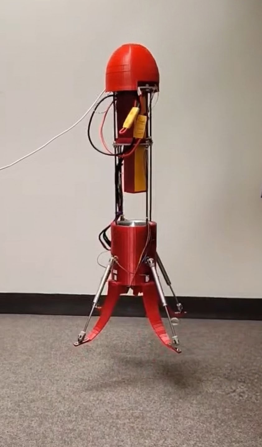
RTLS vehicle completing an autonomous constrained-hover test
Autonomous constrained-hover testing of the final vehicle.
4.605 kg Final mass
5.9 kgf Measured thrust
1.28 Tested thrust-to-weight
Autonomous Constrained hover

Project overview

Building an RTLS test vehicle

The project centered on an electric vehicle designed to take off vertically, stabilize in hover, translate laterally, and return to a designated landing area.

The physical vehicle, named Neo, was paired with a MATLAB and Simulink digital twin named Morpheus. The model represented the vehicle’s forces, moments, actuators, and flight dynamics.
My role

Hands-on chief engineering

My role extended beyond team coordination. I worked across requirements, trade studies, CAD, controls, simulation, wiring, assembly, integration, testing, and troubleshooting.

I also coordinated the interfaces between propulsion, structures, GNC, avionics, and the digital twin throughout the project.

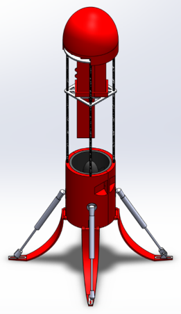
CAD model of the RTLS electric vertical-flight testbed
Final vehicle configuration before assembly.

System design

How the vehicle worked

Electric propulsion

A 105 mm electric ducted fan and 12S LiPo battery provided the vehicle’s lift.

Control guide vanes

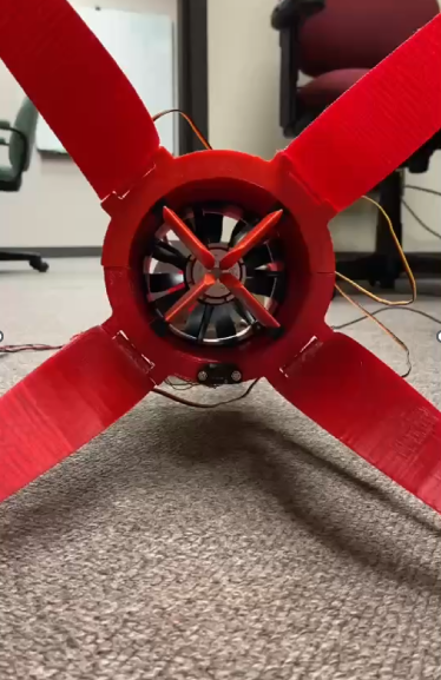
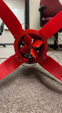
Four servo-actuated vanes redirected the EDF exhaust to generate pitch, roll, and yaw moments.

Onboard avionics

A Pixhawk 6X integrated inertial, GPS, and LiDAR measurements with the autonomous controller.

Digital twin

Simulink models represented the vehicle’s six-degree-of-freedom motion and control response.

Technical highlights

Two decisions that shaped the vehicle

Propulsion

Testing the actual thrust

Theoretical 7.4 kgf
Measured 5.9 kgf

At 4.605 kg, the vehicle required approximately 45.2 N of thrust to hover. Bench testing found less thrust than the theoretical rating, but still produced a tested thrust-to-weight ratio of approximately 1.28.

Thover = mg ≈ 45.2 N

Attitude control

Increasing control authority

15° Pitch disturbance recovery target

The guide vanes were designed to recover from a 15-degree pitch disturbance within one second. Initial analysis showed that the original vane area could not sufficiently counter the EDF reaction torque.

The surface area was doubled, increasing the modeled maximum lift from approximately 3.3 N to 7 N per vane.

Testing and validation

System Integration and Hover Testing

Testing progressed in stages so that propulsion, actuation, and control problems could be addressed before the complete system was powered.

  1. 01

    EDF testing

    Measured thrust and reaction torque across the throttle range.

  2. 02

    Actuator testing

    Verified servo response, vane direction, and range of motion.

  3. 03

    Auto-leveling

    Tested autonomous corrective control-vane commands.

  4. 04

    Constrained hover

    Integrated propulsion, sensing, actuation, and control.

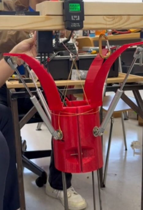
RTLS vehicle undergoing EDF thrust testing
Measuring physical propulsion performance.
Control guide vanes in their neutral position Neutral
Control guide vanes in a commanded deflected position Commanded
Control guide vanes in neutral and commanded positions.

What I learned

Hardware Testing and System Integration

This project taught me that hardware testing is essential and that integration is often the most difficult part of development. Analysis and manufacturer specifications gave us a starting point, but the physical vehicle exposed problems that were impossible to see on paper. Bringing propulsion, structures, avionics, sensing, and controls together required repeated testing and adjustment before the system could operate as intended.

Return to all projects